Our products measure the thickness of concrete plates and slabs according to ASTM Standard C 1383-98a. They can also measure the depth of surface-opening cracks and determine the location, depth and extent of cracks, voids, delaminations, honeycombing and debonding in plain and reinforced structures. For a description of the method, see our Technology page.
Instrument Components
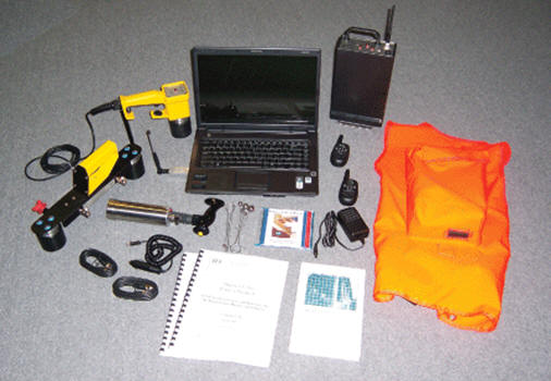
The picture and numbered list below describe components available for an impact-echo instrument. Configuring an instrument consists of selecting the number and types of transducers (items 2-4). These are described on the next page, together with suggested instrument configurations.
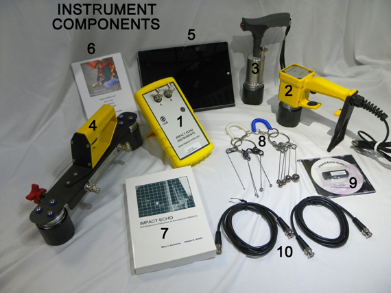
1. Signal Processor: Receives, filters and digitizes signals from the transducers and sends signal data to the tablet computer.
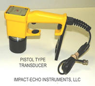
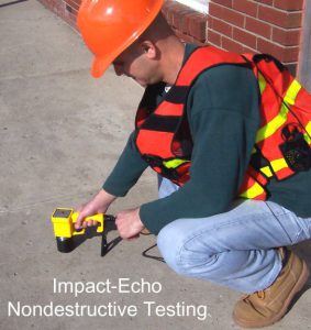
2. Pistol Transducer: Self-standing transducer detects signals generated by multiple reflections of stress waves in structures.
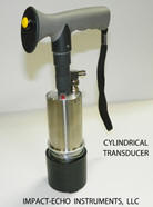
3. Cylindrical Transducer: Patented self-standing transducer detects signals generated by multiple reflections of stress waves in structures.
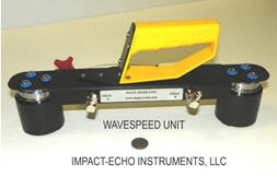
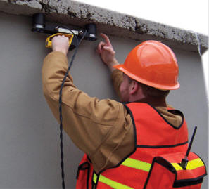
4. WaveSpeed Transducer: Dual head transducer used to measure wave speed by recording the travel time of a stress wave between two transducer tips according to ASTM Standard C 1383-98a.
5. Windows 10 Touch tablet computer (Microsoft Surface).
6. Quick Start Guide and Instructions
7. Textbook: “Impact-Echo: Nondestructive Evaluation of Concrete and Masonry” by M.J. Sansalone and Willima B. Streett (24 Chapters, 339 pgs)
8. Impactors: A set of 10 hardened steel spheres on spring rods used to generate stress waves in masonry structures.
9. Impact-Echo Software: Provided on USB thumbdrive and CD-ROM disk
10. Pair of BNC cables
Transducer Types
The cylindrical transducer (below left) and the pistol-grip transducer (center) are used for impact-echo testing. The cylindrical model is useful for testing in narrow and confined spaces; the pistol-grip model is easier to use and is well suited for flat surfaces. A test instrument must have at least one of these transducers. The Wavespeed unit (dual-head) on the right is used only for independent measurements of wave speed. Such a test is required for determining plate or slab thickness in accordance with ASTM Standard C 1381-98a. Wave speed can be measured using a single cylindrical or pistol-grip transducer if tests can be performed on a slab of precisely known thickness in a region of the structure where testing will be done.
Products and Options
The following are six recommended configurations for an impact-echo test system depending upon the types of tests to be performed.
System A : A comprehensive system having three transducers including two cylindrical or two pistol grip or one of each, plus a dual-head transducer. The cylindrical and pistol grip transducers can be used for testing, with a backup available in case one is lost or damaged. Determining the depth of surface-opening cracks requires two transducers, and is most convenient using two cylindrical or two pistol grip transducers, or one of each. The dual-head transducer is used for independent measurements of wave speed. The picture at the top of this page shows the components of this system (tablet computer optional).
System B: A system that includes the pistol transducer for testing and the dual-head transducer for wave speed measurements. This will cover all possible testing needs. For determining the depth of surface opening cracks, one end of the dual head transducer can be used in conjunction with the pistol transducer. The dual head transducer is used for independent measurements of wave speed.
System C: A system that includes only one transducer, either cylindrical or pistol grip. This system is suitable for routine testing where wave speed is estimated or measured. Wave speed can be measured only if tests can be performed on slabs of known thickness in the regions where testing is to be performed.
The photographs below show testing with a pistol transducer (left) and independent measurements of wave speed (right).
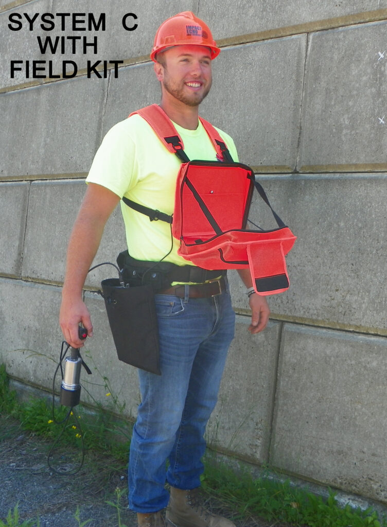
Mobile Basic System: The perfect system for those working alone in the field. This system includes all of the components of the System C (above) with the addition of a chest-mounted touch tablet (Microsoft Surface) running our Impact-Echo software on Windows 10. The tablet is located in the zippered drop-down front of the case, and has adjustable side straps to keep it at a comfortable working angle. The signal processor is carried in a holster and the transducer attaches to a D-ring on the vest when not in use.
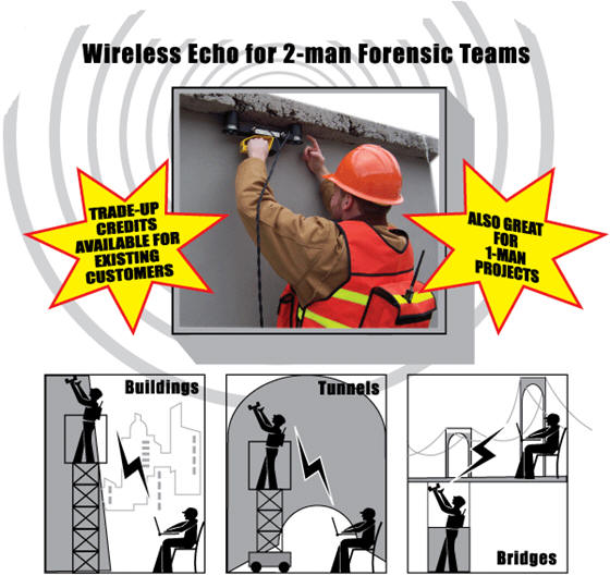
Wireless System: Our specialized system is designed for 2-man forensic teams working in difficult field environments as illustrated below. One operator uses the testing device (transducer) on the structure being tested, and the signals are instantaneously sent by wireless transmission to the computer, where the second operator sees the resulting signals on the touch tablet screen and can make immediate analyses and decisions about where to next test. The wireless system is effective for distances up to 300 meters between operators, and it includes two “fireman’s radios” for continuous communication between operators during testing. In the figure below the testing operator is carrying the signal processor in a backpack which is included with the system.
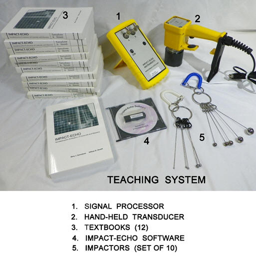
Teaching System: Impact-Echo Instruments introduces an integrated Teaching System to be utilized by universities and technical institutes for teaching the fundamental theory of impact-echo while giving students a hands-on laboratory experience. The Teaching System consists of a pistol-type transducer, signal processor, impactor set, Windows 10 software and 12 textbooks written by the leading authorities in the development and application of the art. The book contains 24 chapters which cover a wide array of impact-echo applications. (See description of the book here which was written by the founders of Impact-Echo Instruments.)
Impact-E Software: All systems include a self-teaching course, the textbook and the Impact-E Windows-based software. Most engineers explain that they become proficient with the software in 4 to 5 hours after working with the self-teaching materials. The software has been recently augmented to provide 3D mapping of composite structures that helps to visualize the relative locations of flaws.

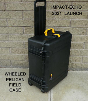
Ruggedized Field Case: All of our systems (except teaching system) include a ruggedized, field case that is dustproof, waterproof and dent proof. The wheeled case has a collapsing handle and individualized component compartment as shown below
ASTM Standard C 1383-98a
The instrument in the configurations shown above can measure P-wave speed and concrete thickness according to Standard C 1383-98a, “Standard Test Method for Measuring the P-Wave Speed and the Thickness of Concrete Plates Using the Impact-Echo Method”, published by the AMERICAN SOCIETY FOR TESTING AND MATERIALS (ASTM).
Specifications & Warranty: View warranty and compliance provisions.